

Description:
The IQ+ is essential two receptors in one Radio. Both receptors have independent antennas input and audio outputs in IQ pairs. They are "lock" with the same local Oscillator preserving same amplitud and phase as a condition for Adaptive Polarization systems. The output of each receptor (2 audio channels) are connected to a Delta44 audio card or similar to do the A/D conversion.
For the A/D conversion the PC need a copy of Linrad (under Linux or Windows), Linrad homepage. For CW Linrad will be enough giving an extraordinary experience with the most powerfull noise blanker and filters, If digital communication is required you will need a copy of MAP65, WSJT homepage. Additional IQ+ is compatible with any software with Si570 routines to control the LO but is specially design to work with Linrad and MAP65. Becouse the LO is based on the Silicon Labs chip Si570BBB existing a big number of SDR programs capable to manage this chip via the USB port but keep in your mind at the moment the only two software with real Adaptive polarization capability are Linrad and MAP65, ther otherones works but only in single channel configuration.
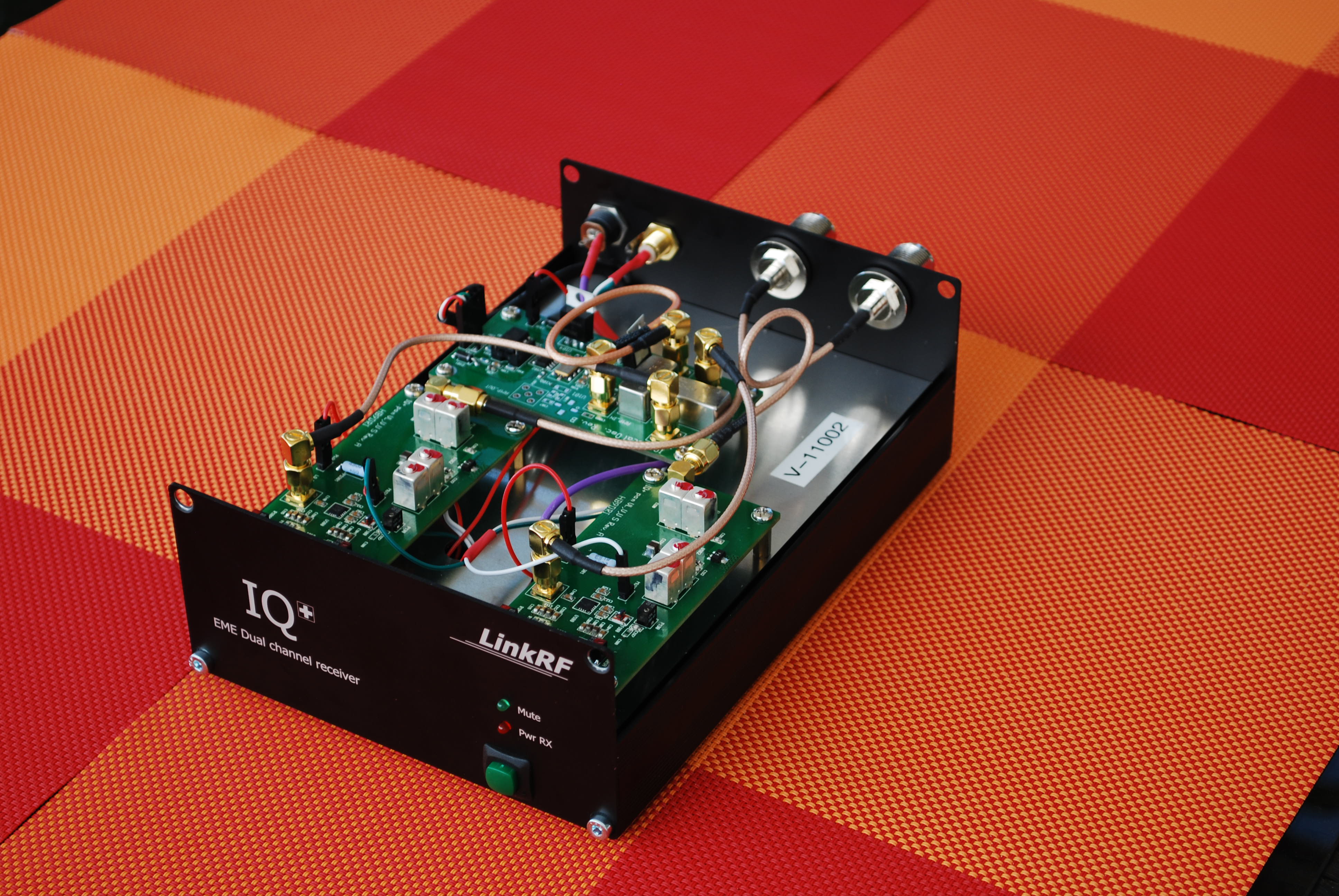
IQ+ Dual RX Radio for Adaptive Polarization
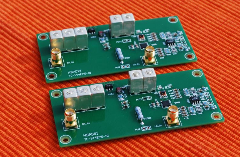
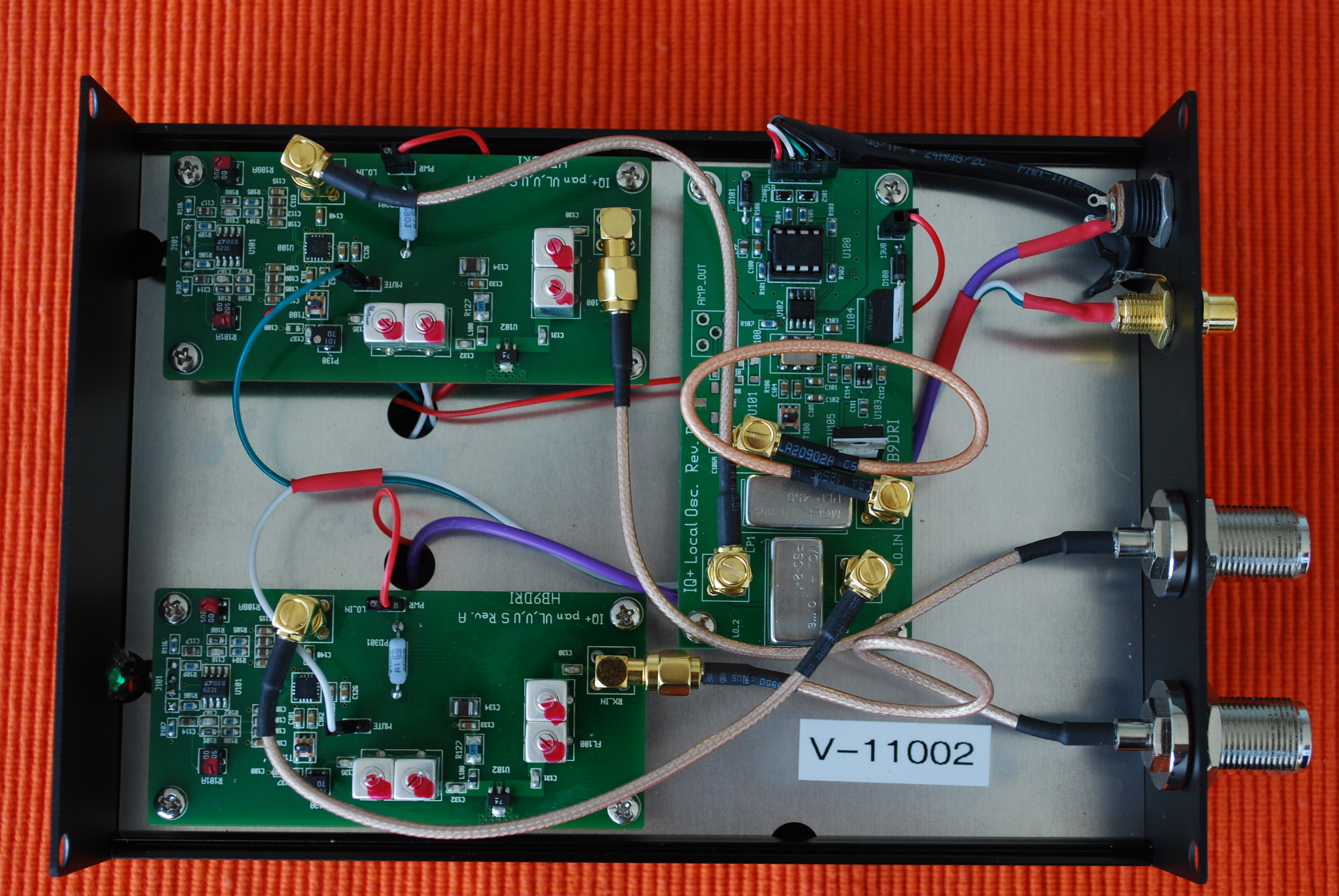
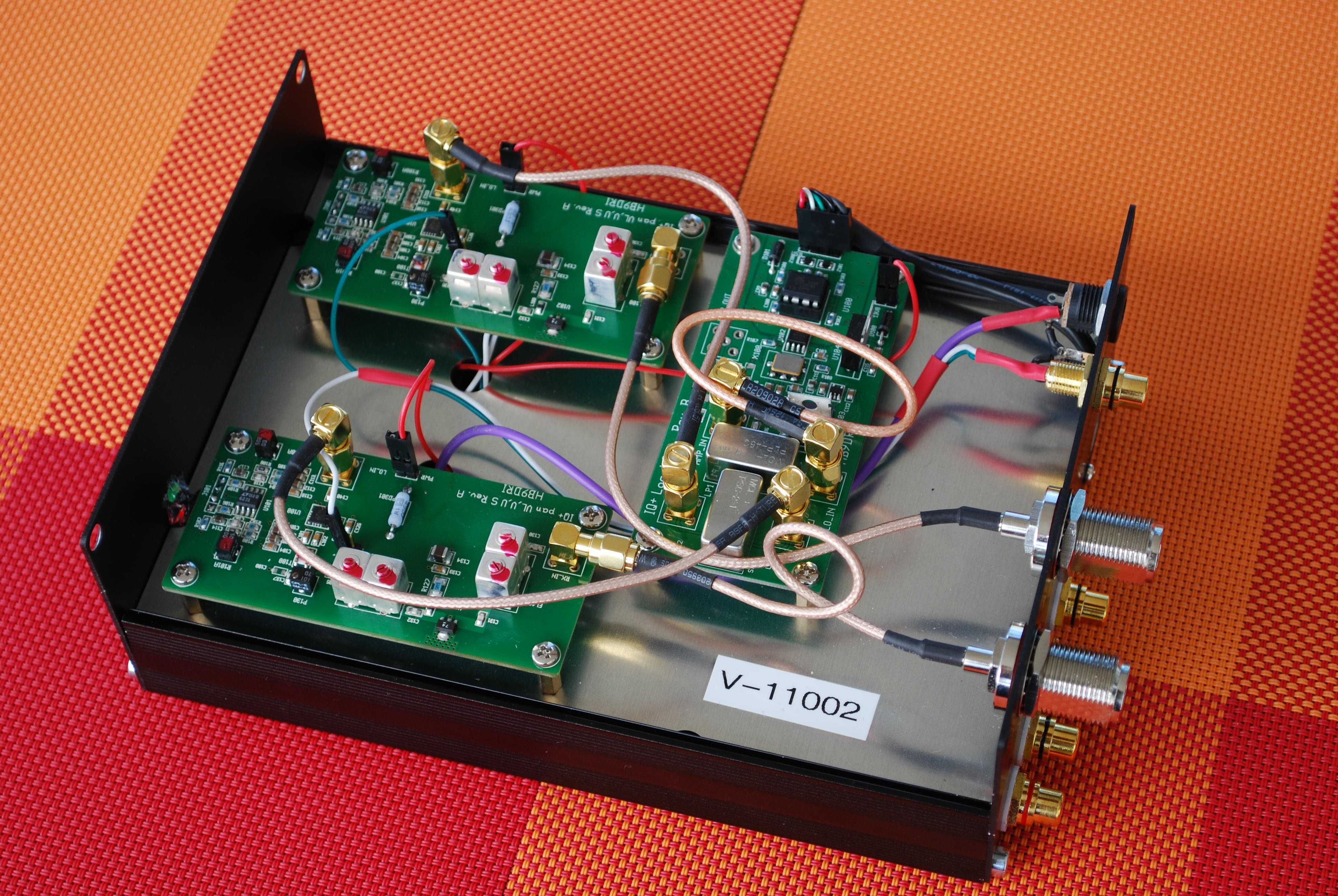
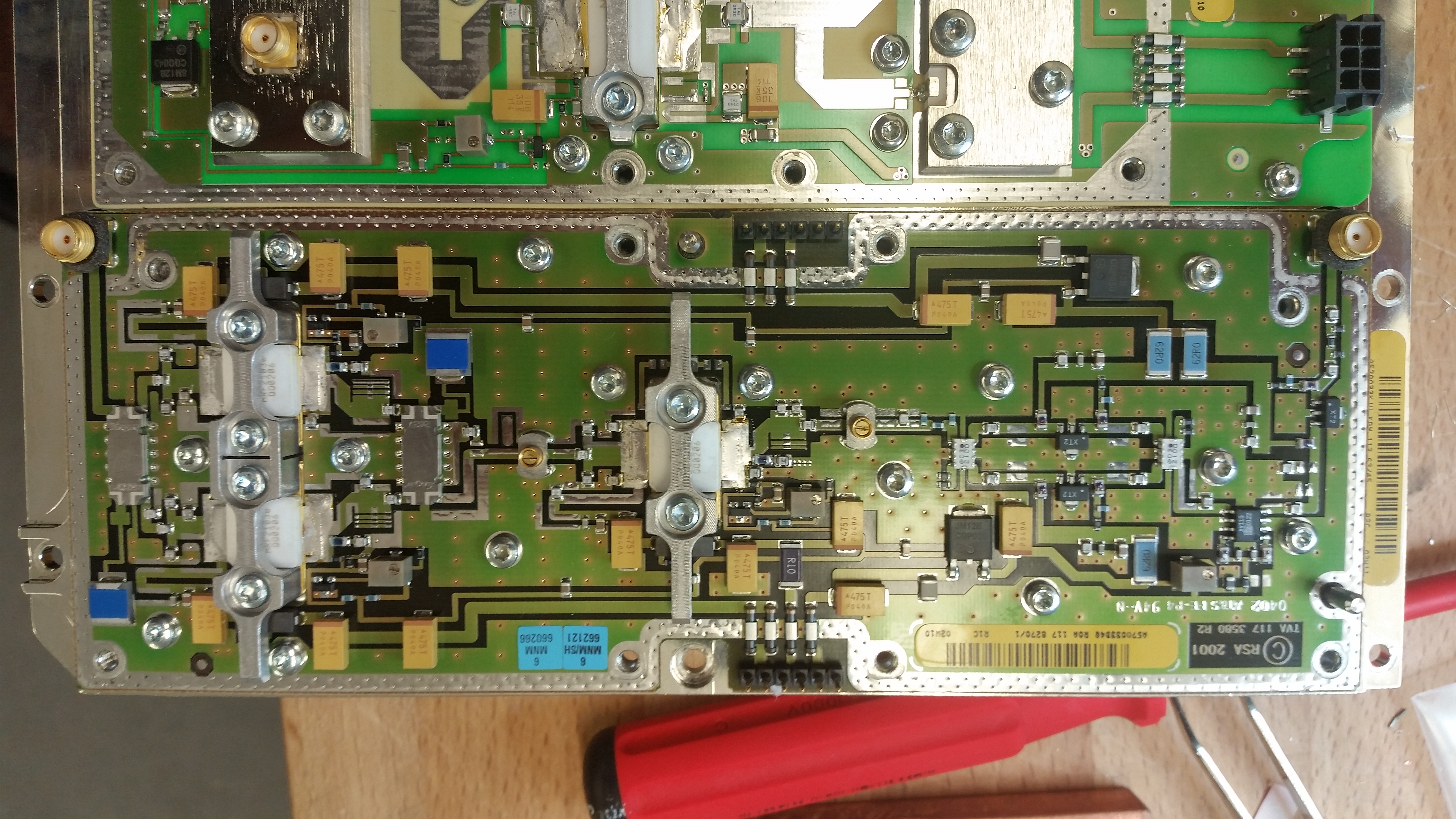
Proto1 IQ+ boards, each PCB is one RX channel, the final design have a 2 cavity Helical input filter insted of 3
(photo as a reference, changes without notice)
The IQ+ RX Board
The next block diagram show the main structure in an IQ+ board. The core is the IQ demodulator from Linear; the LT5517. Existing some applications examples on the web but all the desing I study didn't consider the presence of and external preamplifier. Most implementations lack in an inadequate distribution of the noise increment in the inter stages. This is the reason why I introduce a gain control after the internal amplifier: to regulate the noise contribution without destroying the Dynamic range. At that point the most frecuent failure is to much gain. The GALI74 was selected becouse have very good IP3 (+38dBm) and arround 25 dB gain in 144MHz. With that performance exist enough space to attenuate the gain before the IQ demodulator (this attenuation also afect in a negative way the IP3 but +38dBm is big enough to down some dB's, its always a compromise)
The LT5517 have and extraordinary performance, I decide to use this small 4x4mm integrated because the mixers are well constructed and the phase shifting is almost perfect.
This are the main features of the LT5517:
- RF Input Frequency Range: 40MHz to 900MHz (I test from 3.5MHz to 1.3GHz and works)
- High IIP3: 21dBm at 800MHz
- High IIP2: 58dBm at 800MHz
- I/Q Gain Mismatch: 0.3dB Max
- I/Q Phase Mismatch: 0.7�
- Noise Figure: 12.4dB at 800MHz
- Conversion Gain: 3.3dB at 800MHz
- Baseband Bandwidth: 130MHz
- Single Ended, 50 ohms Matched 2XLO Input
- Shutdown Mode
- 16-Lead QFN (4mm � 4mm) Package
with Exposed Pad
The LT5517 internal diagram:
IQ+ Rev.B. compare with the RevA incorporate several improvements, better SFDR, the central spur is almost eliminated. The Low noise Op-amps works at the double DC voltage but keep the advantage of single power supply. A normal 25dB preamplifier will give the properly noise increment to keep sensitivity and Dynamic range.


Copyright © 2008-2024, Eich Switzerland by Alex Artieda, HB9DRI


EME and Weak signal communication
LinkRF